

Coefficient of Thermal Expansion (CTE) Measurements with Foil Strain Gages
Warning: Following the steps outlined in this recipe makes determining the CTE of any material quick, simple and accurate.
Knowing the coefficient of thermal expansion (CTE) is a common requirement when studying the mechanical deformation of structural materials. If the CTE for your particular material has not been previously measured and published for reference, then accurately measuring this material property is straight-forward using foil strain gage sensors.
In the following sections we detail the steps necessary to make CTE measurements. Before starting, it should be stated that determining the CTE of isotropic materials is simpler than determining the CTE for anisotropic materials (like some composites), since by definition the CTE properties for anisotropic materials can vary with direction.
The first consideration is the type of strain gage sensors needed for this technique. Because of their rugged nature and ready availability, Micro-Measurements’ CEA-Series gages are the best choice for CTE measurements over the temperature range of 100 °F to 150 °F. For temperatures outside this range, WK-Series gages are preferred. However, WK gages may create local reinforcement when working with softer and/or thinner materials, thus altering the CTE measurement. A grid resistance of 350 ohms or higher is preferred since this minimizes possible grid self-heating, which can negatively affect the strain data accuracy. An STC of 06 or 13 is commonly used. Since these two values are often available from stock and the actual STC value is relatively unimportant to the measurement. Much more important is the STC matching between the gages, or very accurate characterization of the strain gage temperature response.
Measurement Process
- Select two stress analysis strain gage sensors from the same package, preferably 1/8-inch gage length, or longer, and 350 ohms, or higher. Note: for improved accuracy, use a dual-grid gage pattern like the 125MG and cut the pattern into two separate gages. This assures nearly identical gage behavior.
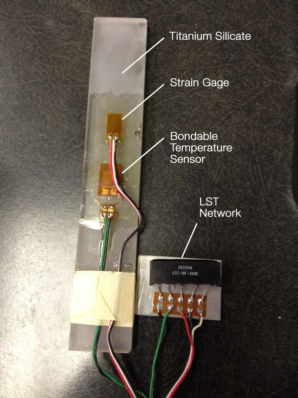
- Bond one of the two strain gage sensors to a titanium silicate bar (TSB-1), available from Micro-Measurements, using M-Bond 600 or 610 adhesive to create a very thin glue-line, which is optimal for CTE measurements. Titanium silicate is used as a reference material, because it has a CTE close to zero, resulting in a convenient reference point.
- With the same adhesive, bond the second gage to the material with unknown CTE.
- Using two bondable temperature sensors (RTDs), bond one to the TSB-1 bar next to the strain gage sensor and bond the second temperature sensor to the material with undetermined CTE, also next to the strain gage.
- Using a 3-wire connection to each strain gage sensor and to the RTD (assuming use of an LST network), then based on the temperature range of the test, add an appropriate protective coating over the gages, RTDs, and lead wire connections.
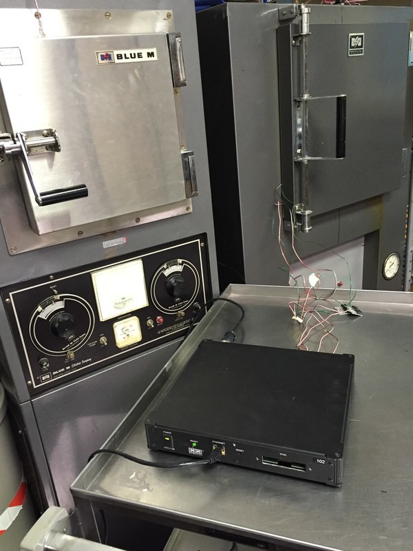
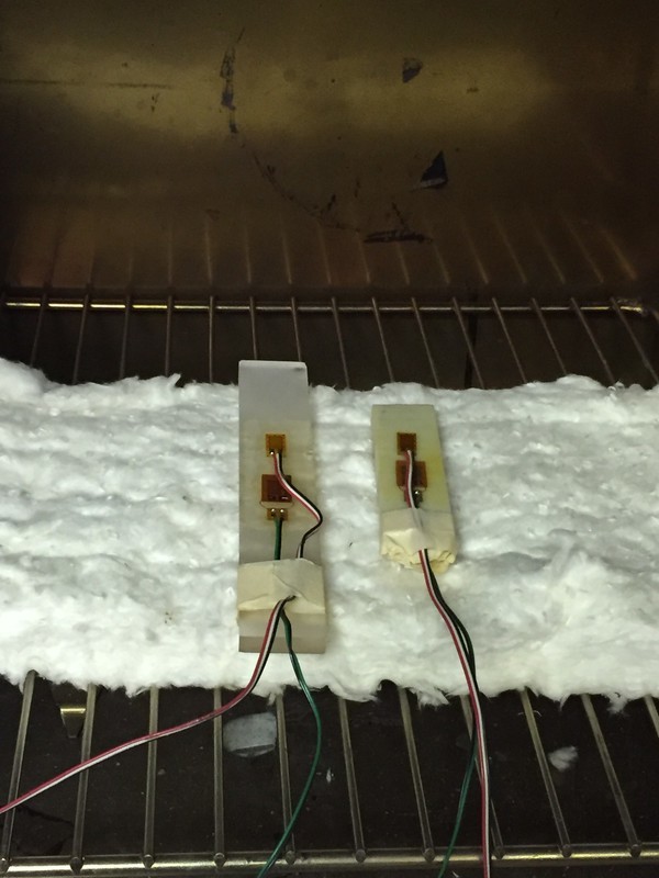
- Place both specimens in an oven and heat cycle 2 or 3 times at 10 °F above max test temperature and 10 °F below min test temperature.
- Using the instrument zero-balance function, zero the two gage readings at room temperature and then ramp the oven to the desired test temperature, ensuring thermal stabilization of specimens, gages, and wiring. Once stable, take readings from both specimens (the RTD readings should be equal from both specimens)
- Subtract the reading from the gage mounted on the TSB-1 bar from the reading of the gage mounted on the test specimen
,and then divide by the temperature change (ΔT). The result is the CTE of the unknown material in ppm/°F.
Example
Reading from TSB-1 gage at +140 °F is +105 microstrain. Reading from the gage mounted to unknown material at +140 °F is +1122 microstrain. Resulting in a CTE for the unknown material of (1122-105)/(140-75), or 15.65 ppm/°F.
The following test was performed using Micro-Measurements’ System 8000 scanner along with a TSB-1 specimen and an unknown fiber reinforced polymer. 350-ohm, ¼-inch gage length strain gages from the same package are bonded to both specimens . As discussed previously, an RTD is also bonded to each specimen. The specimens were placed in an oven on a fiberglass mat to minimize frictional restrictions on expansion during the temperature excursion.
|
||||||
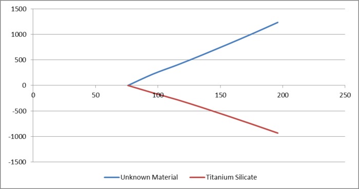
The test data below were generated by taking strain readings at 20 °F increments over the temperature range of +76 °F to +196 °F. The oven temperature and the RTD temperatures were monitored to assure that each reading was the same before data were collected. The chart below shows the various temperature readings and the corresponding CTE computation for both the TSB-1 bar and the unknown material. As seen in the chart, the coefficient of thermal expansion determined for this particular material over the temperature range of +76 °F to +196 °F is approximately +18 ppm/°F.
|
Following the steps outlined in this instructional article makes determining the CTE of any material quick, simple and accurate. For anisotropic materials, or for any material where knowledge of the directional dependence on CTE is desired, just add bonded strain gages in the directions of interest and compare those results with the readings from the TSB-1. Only one TSB-1 bar is necessary per test, regardless of the number of different test specimens or different directions on a single specimen. Just ensure that the TSB-1 bar, and all strain gages and test specimens are at an accurately known temperature before taking strain readings.
If during the temperature excursion the material being tested develops transverse strains high enough to affect strain data, then transverse sensitivity corrections may be necessary. This is normally more of a concern when testing highly anisotropic materials.
Learn more about transverse sensitivity correction in Micro-Measurements Tech Note TN-509: Errors Due to Transverse Sensitivity in Strain Gages.
Learn more about CTE testing in Micro-Measurements Tech Note TN-513-1: Measurement of Thermal Expansion Coefficient Using Strain Gages.
Click here for access to all Linear Patterns of Micro-Measurements Stress Analysis Strain Gages: http://www.micro-measurements.com/stress-analysis-strain-gages/all-linear-patterns/.


Comments
Artículo muy interesante,