

Use of the Full Wheatstone Bridge in Experimental Stress Analysis
Creating Safer and More Reliable Products with Strain Gauges in a Full Wheatstone Bridge Circuit
The strain gauge sensor converts force, weight, and pressure into a readable measurement that can be used to create a safer and more reliable product. Whether you’re performing stress analysis on a bridge, medical device, or truck chassis, understanding the relationship between strain and Wheatstone Bridge output is essential.
What is the Wheatstone Bridge?
Accurate experimental stress analysis requires the measurement of minute changes in high resolution, strain-induced resistance. When the first bonded electrical resistance strain gauge was invented in the early 1930s, it was clear to engineers that a Wheatstone Bridge circuit was required to provide such a specific measurement.
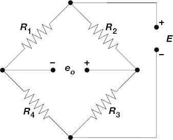
This Wheatstone Bridge, invented by Samuel Hunter Christie in the early nineteenth century, wasn’t brought into regular use until its design was revived by Charles Wheatstone in 1843. The diamond-shaped Wheatstone Bridge circuit (illustrated below) is relatively simple: the four interconnected resistances form a bridge. The principle was to find the value of one unknown resistance as it was connected to other known resistances.
Today, this bridge circuit still provides the most convenient method for measuring and scaling resistance changes during structural testing.
The Relationship between Strain and Wheatstone Bridge Output
Even among engineers who regularly use strain gauges, the relationship between strain and bridge output is a common source of confusion. To explain it in simple terms, we'll describe the output of a strain gage bridge circuit—assuming the strain gage has a gage factor of 2.0—in the formula below:
(0.5 µV / V / µɛ) X N, where N = the number of active arms
As shown in the formula above, the Wheatstone Bridge circuit has four resistance elements, or arms: R1, R2, R3, and R4. These arms can be replaced by one, two, or four strain gages, or active arms. A bridge circuit with one strain gage and three fixed resistors is called a quarter-bridge, since one-fourth of the four arms are strain gages. If two of the arms are strain gages, we refer to the circuit as a half-bridge, and if all four of the arms are strain gauges, we refer to the circuit as a full-bridge.
In experimental stress analysis, the most common bridge circuit employed is a quarter-bridge. In this case, the output of the circuit is determined by the following formula:
(0.5 µV / V / µɛ) X 1
If the supplied excitation voltage is 10 VDC, then the output will be 5 µV per µɛ.
In load cells and other transducer applications, the OEM manufacturer typically chooses to use a full-bridge configuration. In the case of a full-bending bridge, the output of the bridge circuit will be determined by the following formula: (0.5 µV / V / µɛ) X 4.
If the excitation voltage is 10 VDC, then the output will be 20 µV per µɛ.
Most load cells and transducers are manufactured so the full-scale rated mechanical load will produce 1000 µɛ at the gage locations. The full-scale output is calculated as:
0.5 X 10 X 1000 X 4 = 20,000 µV or 20 mV.
Typically, transducers express calibration in mV/V at full scale. This is where the common expression of 2 mV/V for 1000 µε for this device originates.
Not all full bridges are N = 4, however. For a full Poisson (axial) bridge, N = 2 + (2 X ν) where ν = Poisson’s ration of the material. In circumstances where instrumentation does not provide bridge completion and expects to receive only a full bridge, a single strain gage may be configured with a bridge completion module to create a full bridge where N = 1.
Here is an example of a popular Full Wheatstone Bridge Strain Gage:
Other popular Full Wheatstone Strain Gage include:
We’re here to answer any of your questions, or simply chat about all things related to strain gauges and experimental stress analysis. Here’s how to get in touch:
• Subscribe to StrainBlog.
• Watch MM StrainBlog videos on YouTube.
• Follow StrainBlog on Twitter.
• Connect with StrainBlog Editor-in-Chief, Yuval Hernik Bar on LinkedIn.
• Connect with the author, Jim Johnson on LinkedIn.
The author would like to thank Paul Millard for his support and assistance with this article.
Create Safer, More Reliable Products Today. Visit micro-measurements.com
Connect with a Measurement Expert at https://micro-measurements.com/contact


Recent comments