
STRESS ANALYSIS IS LIKE BOXING, IT IS ABOUT THE OBSESSION OF GETTING THE MOST FROM YOURSELF AND YOUR SENSOR WITHIN FOUR ROUNDS
STRAIN GAGE INSTALLATION AND PROTECTION IN FIELD ENVIRONMENTS
Introduction
Field installation of strain gages presents the stress analyst with several unique “problems”, particularly when long-term measurements are required, and massive structures or inclement weather are encountered.
For example, in some field conditions, “proper” surface preparation may be difficult or impossible, and required adhesive curing temperatures may not be attainable.
The article outlines recommendations for gage and leadwire selection, installation and protective coatings to maximize strain gage performance under these conditions. Wherever possible, preparation of the test-part surface should be in accordance with procedures outlined in Application Note B-129. Surface preparation of an area extending at least 2 in [50 mm] beyond each edge of the strain gage will provide an optimum bonding surface for both the adhesive and the protective coating. In some instances these procedures may necessarily be adapted to field conditions, bearing in mind that where some steps are shortened or eliminated, gage performance and service life may be reduced.

Gage Selection (Round one)
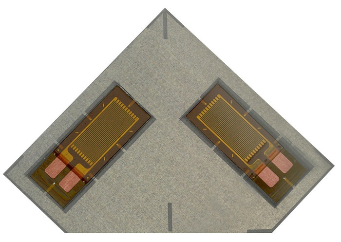
Bondable Strain Gages
Adhesively bonded strain gages are preferred over weldable strain gages when highest accuracy is desired.
When an adhesive cure is possible, select gages from the CEA-, L2A and C2A Series; the EA-, WA-, or WK-Series with Option W; the CEA-Series with Option P2; or the EA-Series with Option P.
Pressure application to the installation during adhesive cure may require special clamping fixtures. Methods for application of clamping pressure include deadweights, spring fixtures secured with bolts or magnets, rubber bands, spring clamps, and vacuum fixtures. Refer to Application Note TT-610 for strain gage clamping techniques. Adhesive curing temperatures are often attainable with heat lamps, hot air blowers, heat guns, strip heating pads, or heating tape. Cyanoacrylate adhesives, such as M-Bond 200, are popular because of their short-term curing requirements. However, the installation surface must first be warmed to at least +65°F [+20°C] prior to bonding. Because of its sensitivity to moisture absorption, M-Bond 200 is not recommended for field installations exceeding six months.
Weldable Strain Gages
Where structure size or weather conditions will not permit adhesive curing, weldable strain gages are an alternate approach for gage installation.
The Weldable Strain Gage consists of a specially manufactured strain gage prebonded to a metal carrier for spot welding to the test surface. Although weldable gages are more costly than bondable gages, the overall installation cost is reduced significantly because of the shorter installation time and elimination of adhesive-curing temperatures.
With either bondable or weldable strain gages, a fully encapsulated gage type will ensure maximum stability, and a gage resistance of at least 350 ohms will minimize errors associated with leadwire desensitization. When maximum accuracy is required below -50°F [-45°C] or over +150°F [+65°C], modified-Karma (K) alloy is recommended.
Leadwires (Round Two)
Selection
It is important to select the proper wire type and size to help ensure stability of measured data. Moisture absorption through the leadwires can result in apparent gage instability and drift; therefore, the leadwire insulation should be tested for its waterproof properties before installation.
Where long lengths of leadwire are required, select a wire gauge large enough to maintain minimal leadwire resistance, preferably less than 1% of the strain gage resistance. Quarter-bridge gage circuits utilizing a three-wire connection to the instrument are preferred in order to minimize temperature effects and leadwire desensitization.
When lengths of leadwire are spliced together, the splice joints can be protected and waterproofed with a heat-shrinkable wire splice sealant such as HST-1. HST-1 can be used to seal splice connections of stranded, insulated leadwires ranging from 18 to 34 AWG.
For further protection of long-term installations, encasing the leadwire in waterproof conduit is recommended.
Preparation
A common source of gage failure is an inadequate bond between the protective coating and the leadwire insulation (or conduit) in the lead exit area. Without proper seal, moisture can be drawn into the gage area along the leadwires by capillary action. This junction is important to successful long-term strain gage installations.
Vinyl-insulated leadwires should be coated with a layer of M-Coat B, an air-drying nitrile-rubber compound. Untreated Teflon®-insulated leadwires require etching with a Teflon etchant, such as TEC-1 Tetra-Etch® Compound. The conductors of flat-cable leadwire should be separated prior to treatment to assure an even application around each conductor.
Thermally stripping and tinning the leads after treatment prevents contact of the priming materials with bare wires.
Attachment
Field installations often fail because of improper solder selection or inadequate removal of soldering fluxes. Fluxes are generally hygroscopic and, when not completely removed, contribute to gage instability and drift. Rosin fluxes are recommended for strain gage use, and are removed with several applications of RSK Rosin Solvent. Some industrial fluxes, particularly zinc-chloride paste, are not suitable for strain gage soldering. Micro-Measurements solders and fluxes have been selected specifically for this purpose.

Protective Coatings (Round Three)
For maximum stability of the strain gage, the installation requires sealing with a protective coating that is immediately stable chemically, and highly resistant to water-vapor transmission. Mechanical protection is also often required to shield the installation from the effects of earth fills, concrete pours, tool handling, structural assembly, etc.
Moisture is the most common cause of field installation failures. Its presence usually results in low electrical resistance to ground and causes circulating currents, electrical noise, and desensitization of the measurement. Grid corrosion and intragrid conductive paths can also result, causing negative or positive drift in output, depending upon which cause is predominant.
A good protective coating not only seals the gage installation from moisture, but will also seal in any moisture in the area at the time of coating application. For maximum stability in high-moisture environments, it is therefore important to warm the gage installation until any moisture is removed prior to applying the protective coating. The protective coating should be applied immediately after gage and leadwire installation to prevent moisture from collecting in the gage area.
The M-Coat F protective coating system is an excellent choice for immediate and thorough protection in field environments. There is no cure requirement for M-Coat F. Refer to Instruction Bulletin B-134 for specifications and application instructions for the M-Coat F system. Another popular coating for field environments is M-Coat JA. M-Coat JA is a polysulfide rubber compound that is easily mixed and cures to a hard rubber material that offers excellent mechanical and moisture protection. Refer to Instruction Bulletin B-147 for M-Coat JA application.
Data Acquisition (Round Four)
A properly installed and protected strain gage installation does not alone ensure stable, drift-free measurements in hostile field environments. Instrumentation and temperature changes at the gage location can influence strain measurements.
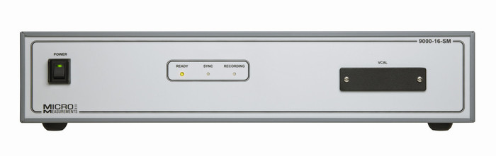
Instrumentation
Portable instruments are ideal for field measurements, but they require special consideration to maintain accuracy and repeatability. Battery-powered models should employ battery-check circuits to assure proper sensitivity and proper calibration. In addition, an instrument which powers the gage only during strain measurement assists in gage stability.
To check stability over long periods, an instrument zero-reference channel is recommended. Zero-reference channels are generally single- or full-bridge precision resistors that can be connected to the instrument before and after each measurement sequence to check the zero stability.
If leadwires will be disconnected from the instrument between measurements, sealing the tinned ends when not in use will prevent moisture absorption. Sealing can be accomplished by dipping the lead ends in melted wax, or encasing in a waterproof junction box. When solderless connectors are selected, they should have low and repeatable contact resistance.
Temperature Effects
Self-temperature-compensated strain gages are recommended for single-gage measurements. A properly installed and wired gage of this type will typically result in a thermal output of less than 50µε over a range of +40° to +125°F [+5° to + 50°C]. Where expected temperature ranges will be wider, or where higher accuracy is desired, a surface temperature measurement taken at the gage location with each strain measurement can be used with the gage-package data to correct the strain gage readings for effects of temperature. Where feasible, a temperature-compensating half-bridge gage installation can be used as an alternate method of temperature compensation, and may be preferred in some applications.


Recent comments