

A Step-By-Step Guide to Designing Your Dream Sensor.
The initial step in preparing to measure any strain or force is the selection of the appropriate strain gage sensor. The careful, rational selection of strain gage characteristics and parameters can be very important for optimizing the strain gage performance for specified environmental and operating conditions, obtaining accurate and reliable measurements, contributing to the ease of installation, and minimizing the total cost of the gage installation. Micro-Measurements offers a wide variety of strain gage sensor constructions and designs for stress analysis as well as transducer applications (OEM). In some instances, selecting a catalog strain gage is not enough, since certain applications may require a custom strain gage. Micro-Measurements produces hundreds of custom strain gage sensors for both stress analysis applications as well as transducers.
Obtaining a quotation for a custom strain gage is easy. Our Engineering team just requires a simple sketch of the strain gage layout showing the critical dimensions, preferred connection pads location and desired strain measurement direction. This sketch can be hand drawn and does not need to be formal. We also need to know the gage operating temperature range as well as the desired grid resistance(s). After receiving this information, our Application Engineers will define the technical specifications and create a formal drawing of the strain gage which will be provided to the customer by our customer service representatives (CSR) along with a quotation for approval. Once approved by the user, a new part number will be assigned to the custom strain gage for ordering / tracking within our MRP system. Typically new strain gage designs require a one-time set-up charge. A typical custom stress analysis strain gage may be similar to a catalog gage except for perhaps a non-standard resistance, custom alignment marks, special lead wire or oversize/relocated soldering tabs.
Custom Transducer-Class strain gages built with Advanced Sensors Technology may have similar features as stress analysis gages. However, more often, than not the custom features that are requested are designed to reduce installation labor, provide sensor redundancy and increase reliability by reducing then number of solder junctions. Custom features may include pre-applied adhesive on the gage backing, tray packaging for fast gage handling / removal, dual grids with custom spacing, or even multiple gage grids interconnected as one “assembly” using flexible PCB or common backing.
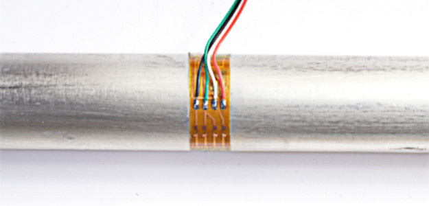
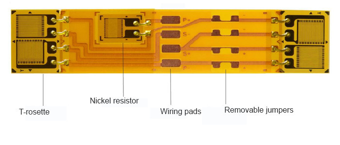
For example, strain gage transducers typically employ a set array of strain gages, resistor(s) and terminals that require precise manual placement and highly skilled wiring / soldering operations to complete the Wheatstone bridge circuit including balance and compensating resistors. This is a labor intensive operation, both for component positioning and for wiring. For high volume production applications, having all of these connections made on the strain gage itself can be a distinct advantage by reducing installation labor, eliminating rework and increasing reliability. Typical examples are compact full bridge diaphragm strain gages where the gage grids are closely spaced. On larger transducers, the strain gage locations would require a strain gage pattern that is too large to be economically feasible. This is where an assembled strain gage on flexible PCB can be helpful. The picture below shows a strain gage assembly, complete with a nickel resistor for modulus compensation . This design is for use on a 1 inch (25mm) diameter tube that is loaded in tension/compression. Two T-rosettes are located at the required spacing to place them 180 degrees apart on the tube after installation. They are pre-connected to a flexible terminal strip which includes a nickel resistor for modulus compensation, wiring pads, and four removable jumpers (see below) connected to the Wheatstone bridge corners for zero and zero TC correction. When compensation is required (determined after initial testing) any one of the four corners can be opened by cutting the connecting bar. Once opened, a compensating wire may be added as needed.
Printed circuit terminations are another popular option for both transducer and stress analysis applications. This option provides for remote leadwire termination, away from the gage location, and is particularly useful in applications with difficult access to the bonded gage, or when having solder connections near the gage would either compromise the testing or complicate the final assembly of the structure. For example, a small strain gage assembly, which includes a temperature sensor and long printed circuit termination, works well when testing the combustion area of an internal combustion engine cylinder head. The gage assembly can be kept small and especially thin, with the printed circuit easily sandwiching between the head and block, providing external leadwire attachment.
Due to their uniqueness, all assembled strain gages are customized for each application. We would be pleased to offer a quotation if your application requires for such design.
Application: Commercial aircraft flight test qualification
Project: Custom strain gages installed on an existing aircraft landing gear actuator to measure tension, compression and bending loads during take offs and landings.
Activity: First, Micro-Measurements obtained approval of our quality system and gage installation procedure from a well-known aircraft manufacturer. Second, we then provided a quick-turn service for the custom strain gage design, production and installation on the actuators in time to meet flight test deadlines.
Application: Exercise equipment (rowing machine)
Project: Supply a low cost custom force sensor for installation at the end of a shock absorber to provide real time load data. The data, along with stroke displacement, allow for calculation and display of calorie burn rate and total calories burned during the workout.
Activity: The sensor element was machined from high strength aluminum bar stock. A half bridge (2 element) foil strain gage (gauge) was bonded to the flat end of the sensor body and covered with a protective elastomer. The gage size and design takes advantage of the strain pattern at the end of the sensor.

Application: Aerospace test program
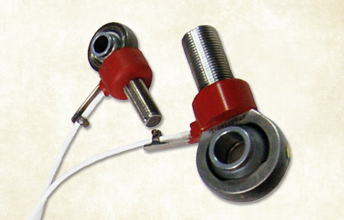
Project: Install strain gages on existing military specification rod ends to measure tension and compression forces on actuators that steer the rocket exhaust nozzle. These sensors collect data during both static and dynamic flight test. Tension output is required to match compression output to within 1%.
Activity: Using commercial off-the-shelf (COTS) strain gage patterns available to meet the accuracy requirements due to bearing shape and space limitations, photoelastic techniques are utilized to determine the strain pattern in the gage location area. We then designed and manufactured a custom strain gage pattern to take advantage of the existing strain field. High temperature potting material and wiring was used to meet operational temperature requirements and the sensors successfully meet all the project requirements.
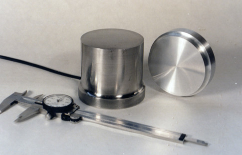
Application: 300 ton swage press
Project: A small sensor (a little over 3 inches in diameter) was needed to measure swage press forces that would survive being placed directly in the jaws of the 300 ton press.
Activity: Since almost everything placed in the jaws will be “smashed,” a sensor was designed and built using a very high strength steel with a minimum amount of material removed to form a stress concentration area for location of the foil strain gages (gauges). A sacrificial aluminum top cap was designed in order to provide a repeatable strain field in the sensor. A photoelastic model was used to determine and verify that a proper strain field would result.


Recent comments