
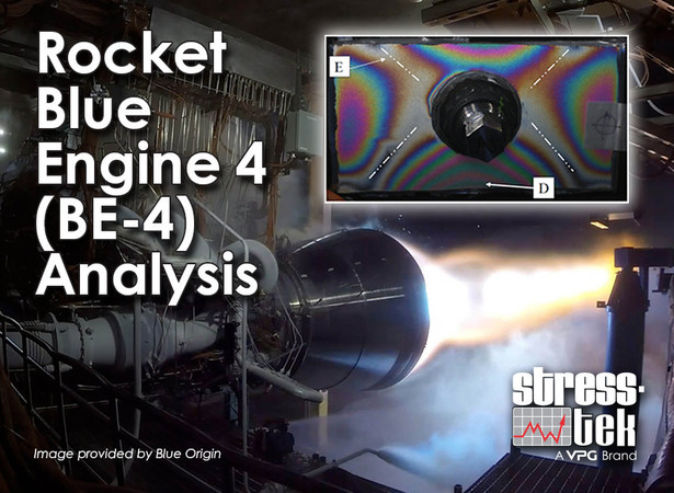
Photoelastic Analysis of Structural Support on Rocket Engine Fuel Line Bellows
Onsite analysis performed by Stress-tek, Inc. August 2020.
The BE-4 Blue Origin rocket engine delivers 550,000 lb. of thrust at sea level using seven engine nozzles to make up the rocket motor. Liquid oxygen is carried through a bellows coupled fuel line to a single combustion chamber and nozzle. This motor uses a high performance thermodynamic architecture similar to the current Atlas V rocket engine.
The bellows function allows fuel line movement under operation while maintaining structural stability. Each fuel line has three bellows that control stability during fuel delivery. The fuel bellows has a stabilizing ring for structural support and to react to engine forces during operation.
Photoelastics was placed on two critical surfaces of the bellows stabilizing ring to observe stresses and stress gradients during loading. Half load and full load conditions were analyzed to obtain a complete understanding of where maximum stresses and critical stress gradients are located.
Stress values are not published in this article due to the application’s sensitivity.
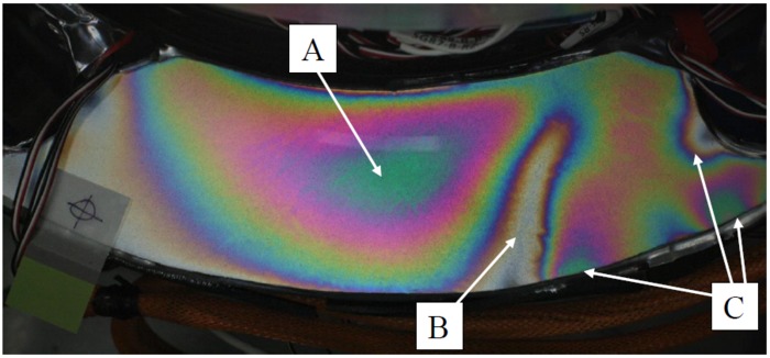
Image 1A: Gusseted Stability Plate Under Half Load
Areas of Interest:
A: The center green area of color is a tension stress field where the maximum stress is in the center of the green color, the tension field expands outward from this central location and the magnitude lessens as is moves away from the center. The white areas (no color) to the left and right of this field define a zero stress field state. If a strain gage is placed near this tension area, but not directly on the maximum, the strain gage would report a stress value – it just would not be the maximum - the maximum stress would go undetected.
B: The white vertical band (no color) is an area of no stress, there is a gusset directly under the plate there and the gusset is supporting the load causing the top surface to be stress free at this location.
C: To the right of the plate shows areas that are under tension on the plate’s edges. Edges under tension are of concern, as these conditions are where cracks tend to originate.
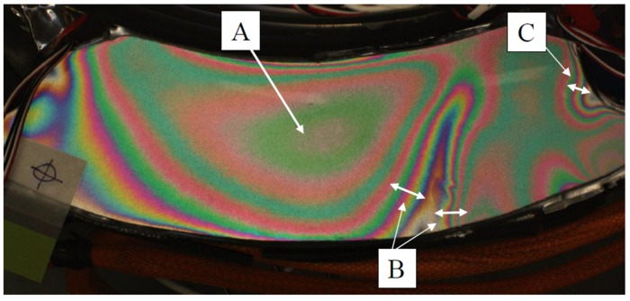
Image 1B: Gusseted Stability Plate Under Full Load
Full load condition clearly shows where the high stress gradients are located.
Areas of interest:
A: Even though the centrally located tension field is high, (illustrated by the many color bands coming out of this point) the broad spaced color bands indicate the gradient is low.
B: In the stress field around the gusseted area (white color indicating no stress) the color bands become tighter indicating the stress gradient is high. If the gusset under the plate was made less stiff, the gradient around it would diminish, creating a less acute stress riser.
C: The right side of the plate has three tension locations on the edge, but the field farthest to the right has tight color bands indicating high gradient. Of the three areas, this one is of the most concern as the high stress gradient on an edge is a location where cracks initiate.
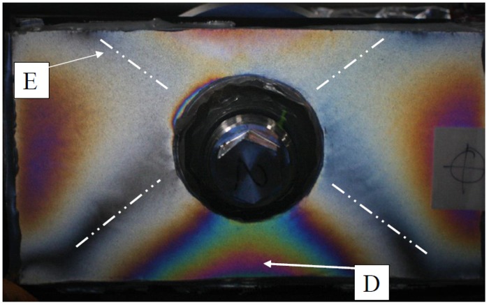
Image 2A: Structural Fastening Joint Under Half Load
Areas of interest:
D: The plate loading creates a biaxial stress field where the lower part is in tension and the upper part is in a lesser magnitude of compression.
E: The white areas (with darkened centers) creating an “X” type pattern are areas of no stress (indicated by the absence of color).
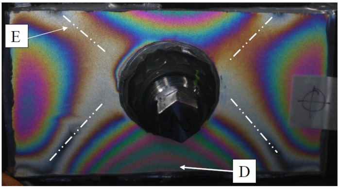
Image 2B: Structural Fastening Joint Under Full Load
Areas of interest:
D: Under maximum load, it’s easy to see that the magnitude of the lower tension field is three times that of the upper compression field. Due to the fastening design, the joint is put under non-symmetrical bending loads causing a large differential between tension and compressive stress magnitudes.
E: The white areas (with slight darkened centers) creating an “X” type pattern is now clearly visible as areas of no stress. It is common for merging tension and compressive stress fields to have areas of no stress; this area is a type of “neutral axis” of bending.
About Stress-tek (https://stress-tek.com)
Stress-tek has extensive experience in the design and manufacturing of strain gage based sensors and load cells, applying strain gages to element bodies and providing stress analysis services. It has complete in-house capability in engineering, machining, assembly, and testing.
Stress-tek was founded in 1978 to provide professional consulting services in the areas of strain gaging, transducer design, and experimental stress analysis. Since then they have evolved to designing and manufacturing of custom and high volume weighing, force measurement, pressure, and deflection sensors requiring accuracy and reliability. The result is an extensive line of shear beam load cells, bending beam load cells, shear pin load cells, tension and compression load cells, deflection transducers, hydraulic and air pressure sensors. Stress-Tek, also designs and manufactures digital, two-wire electronics to integrate with our load cells and sensors to provide complete solutions.
In 2015, Stress-tek became part of Vishay Precision Group, Inc. (VPG), an internationally recognized designer, manufacturer and marketer of sensor and sensor-based measurements systems specializing in the growing markets of stress, force, weight, pressure and measurement. VPG is a market leader of foil technology products, providing ongoing technology innovations in precision foil resistors and foil strain gages, which are the foundation of the company’s force sensors products and its weighing and control systems.


Recent comments