
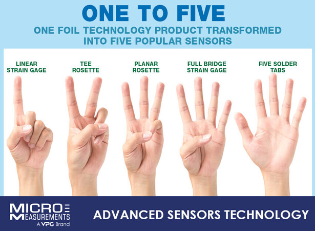
One to Five
One Foil Technology Product Transformed Into Five Popular Sensors.
All strain gage sensor configurations discussed below find many applications in both general purpose testing (stress analysis, like fatigue testing and materials testing) and transducer applications (calibrated devices for measuring specific physical quantities, like scales and accelerometers). The primary difference between the two classifications is gage sensor calibration. General purpose users rely on the strain gage sensor itself to communicate the correct strain on the surface to which the sensor is bonded. This requires the manufacturer to pre-calibrate the strain gage sensors to a high degree of accuracy (typically, ±0.5%) and report this sensitivity on the gage package. In contrast, all transducer applications use a calibrated device to accurately indicate the physical quantity being measured. In these applications, the user is relying on the extremely repeatable nature of strain gage sensors so that every transducer produced has the same relationship to the physical quantity being measured.
Strain Gage Linear Patterns (Uniaxial Stress)
The strain gage pattern refers cumulatively to the shape of the grid, the number and orientation of the grids in a multiple-grid gage, the solder tab configuration, and various construction features which are standard for a particular pattern. The linear pattern strain gages are used to measure strain in a single direction.
TEE ROSETTE, 0° - 90° PATTERNS: DUAL GRID
Bi-axial strain gages, often referred to as Poisson strain gages, are 90° tee rosette gages, aligned with the principal strains in uniaxial stress loading. They are also used extensively in column load cells and simple cantilever beam transducer applications.
T-rosettes are used where the direction of the principle strains are known. Strains at 90° enable calculation of the stresses at the measurement location, not possible with a single strain gage. Commonly used where tensile or compression material property tests are performed, they enable calculation of Poisson’s ratio as well as Young’s modulus. Using a T-rosette for this apparently simple test allows the user to make transverse sensitivity corrections for maximum accuracy of the test results.
In column load cells for example, the Tee Rosette strain gages are utilized to cancel bending strains and for cantilever beam applications, these sensors allow for gaging a single side of the spring element to reduce cost.
The tee rosettes minimize the number of gages needed for testing and provide reduced installation time and potential errors.
Tee rosettes Strain gages are also used to determine the Poisson’s Ratio for a material in accordance with ASTM standards.
They are also used where direct tension measurements, such as a bolt in tension or suspension rod in compression, is desired. A full bridge, produced by using two Tee-rosette strain gages, in this situation minimizes pickup due to bending. Tee rosettes can also be deployed for bending measurements, especially useful on large infrastructure such as wind turbine towers. Adjacent gages on the same backing will see identical temperature and therefore eliminate thermal outputs due to differential temperatures across the structure. Additionally, 45° alignment marks are provided on each T-Rosette gage so it may be accurately applied to a shaft to measure torsion.
3-ELEMENT ROSETTE STRAIN GAGES
A strain gage rosette is, by definition, an arrangement of two or more closely positioned gage grids, separately oriented to measure the normal strains along different directions in the underlying surface of the test part. Rosettes are designed to perform a very practical and important function in experimental stress analysis.
It can be shown that for the not-uncommon case of the general biaxial stress state, with the principal directions unknown, three independent strain measurements (in different directions) are required to determine the principal strains and stresses. Moreover, even when the principal directions are known in advance, two independent strain measurements are needed to obtain the principal strains and stresses.
A FULL (WHEATSTONE) BRIDGE STRAIN GAGE SENSOR
The default construction of a strain gauge transducer uses a full Wheatstone bridge often with multiple backings distributed around the transducer hardware. This offers the best accuracy and insensitivity to off-axis loading, but for lower-cost sensors a single full-bridge pattern can be used. This represents several advantages over two or more backings, the most obvious is the reduced labor to install the strain gauge. The single backing and foil offers better temperature response not just due to the locality of the sensing elements but also because thermal output scatter is virtually eliminated.
The full-bridge circuit (with four active strain gages) provides for the highest measurement sensitivity and the best extraneous temperature cancellation. Built using Micro-Measurements' Advanced Sensors strain gage technology, the full Wheatstone bridge strain gages offer improved grid-resistance tolerance and grid-to-grid temperature matching compared to traditional gages. Micro-Measurements offers a wide range of pattern configurations and resistance ranging from 350 Ω to 20 kΩ. The addition of gold-plated solder pads improves lead wire attachment and solder-joint reliability, reducing the chances of solder pad oxidation prior to attaching the lead wires.
Torque measurement is another common application for full-bridge strain gages. In these applications, the strain gage is used to measure engine power output on propshafts and driveshafts, driver input through steering wheels, tightening bolts, or anywhere a component is subjected to a twisting force. The full bridge circuit is used to double the sensitivity to torque and cancel unwanted effects due to axial or bending load components.
In addition, with all four arms of the Wheatstone bridge being manufactured simultaneously from a single piece of foil, grid-to-grid thermal characteristics are more closely matched, and thermal output is cancelled in the bridge circuit. Micro-Measurements full bridge strain gages are available in a variety of sizes, configurations, and mounting technologies.
5 VS. 4 SOLDER TABS - A FULL BRIDGE STRAIN GAGE ( TRANSDUCER APPLICATIONS)
To measure such small changes in resistance, Advanced Sensors Technology strain gage sensor configurations are based on the idea of a Wheatstone Bridge. The three types of strain gage configurations, quarter-, half-, and full-bridge, are decided by the number of active elements in the Wheatstone bridge, the orientation of the strain gages, and the directions of principal strains.
All full-bridge configurations have four corners, two for power and two for signal. So why are some strain gages designed with four solder tabs and others with five solder tabs? As you will learn from the following video, where Darryl explains about strain gage configurations that have four active grids and are available in different types with 4 or 5 solder tabs.
Five-tab configurations are used when transducer compensation methods are employed. This can include very tight compensations for both temperature and loading influences on the output. If the inherent compensation provided by the closed bridge configuration (4 tab) is sufficient to achieve the desired transducer accuracy over its working temperature range, then the 4 tab configuration reduces installation time and costs by eliminating one solder connection and the associated wiring.


Recent comments