

Fun with Strain Gages and Dimensional Variables
Humans define their existence spatially and temporally. That is, using location and time: “I’m 39 years old,” “I’m moving to Alaska,” “It should take about one-hour to drive the remaining 55 miles.” Including the dimension of time, Physicists searching for a theory-of-everything using M-theory suggest that we live in an 11-dimensional space-time continuum.
But most humans who think about such things tend to limit their domain to 3D plus time; or, breadth, height, and depth, plus time. Using the Cartesian coordinate system, we label these 3-dimensions x, y, and z. Newtonian mechanics plays within those 3 positional dimensions and time. And, the stress analyst plays within Newtonian mechanics using positional-based displacement, deflection, and deformation, and time-based velocity and acceleration.
Engineers often use the three location-based units interchangeably. At the very least, one choice over another is context sensitive; point-deflection; surface-displacement; body-deformation. Although guilty of the aforementioned interchangeable use of these terms, for purposes of this article, the following definitions will be used (with some attempt at consistency).
Displacement – the change in distance between two points of a body caused by an external agent (e.g. force or heat); normally 1-dimensional.
Deflection – the change in location of a point on a body within a fixed coordinate system caused by and external agent (e.g. force or heat); normally 2-dimensional (commonly involves a change in angle).
Deformation – the change in shape of a body caused by an external agent (e.g. force or heat); normally 3-dimensional.
Using standard dimensional units, engineers define a measurable phenomenon called strain as
ε = ΔL/L (1)
where: ε = strain
ΔL = change in length
L = initial length
Electrical resistance strain gages are excellent choices for measuring all of these parameters; albeit, with the aid of a mechanical companion in some cases.
Electrical resistance strain gages are small, flexible sensors that act like variable resistors. The variance occurs when the strain gage changes length. At its resting dimensions, the strain gage has a starting electrical resistance, measured in ohms. As the active grid-length of the strain gage changes dimensionally, the electrical resistance changes proportionally. The constant of proportionality is called gage factor, F, and can be expressed algebraically as
ΔR/R = Fε (2)
where: ΔR = change in resistance
R = initial resistance
F = gage factor
ε = applied strain
To see how the strain gage can be used for indication of changes in length (displacement), Eq. (2) can be expanded into a form not generally used
Rf/Ro = F(Lf/Lo -1 ) + 1 (3)
where: Rf = final resistance
Ro = starting resistance
F = gage factor
Lf = final gage length
Lo = starting gage length
Gage factor is a convenient scaling value when configuring instrumentation commonly used with strain gages. By directly relating relative changes in grid resistance to applied strain, this scaling factor allows the instrument to read directly in strain units, which is the value normally associated with and indicated by bonded electrical resistance strain gages.
But if our desire is to indicate other units, like a change in length, then Eq. (3) can be derived differently to produce the following relationship between length change and resistance change
Lf/Lo = √(Rf/Ro) (4)
where all terms in Eq. (4) are as previously defined. It should be noted that Eq. (4) is a minor approximation, but the length calculation error is very small at <<0.1 ppm.
Armed with Eq. (4) and knowing the initial gage length (Lo) and the initial gage resistance (Ro), then after applying a load to the part on which the gage is bonded, Rf is measured using a sensitive ohmmeter to calculate Lf; which is the change in length of the specimen surface over a distance equal to the gage length of the bonded gage. For reference, this would be the same displacement result obtained using a sensitive moiré grid with a measurement length equal to the gage length of the strain gage. If the specimen is continuous and homogenous and unconstrained except at the fixed end, then the calculated length change can be used to calculate the resulting end-displacement of the part, d (see diagram below).
Another way to measure the end-displacement of this part using strain gages is to build a linear displacement transducer using strain gages as the sensors. Such devices (like the Micro-Measurements Linear Displacement Sensors) have a moveable plunger that deflects an internal structure instrumented with bonded strain gages. Placing the plunger tip against the bottom of the part, as the end of the part moves, the attendant plunger movement is measured by the deflected strain gages. A nice feature of strain gage based displacement sensors is that these devices can be connected directly to strain indicator instrumentation and the instrument scaled to read units of displacement.
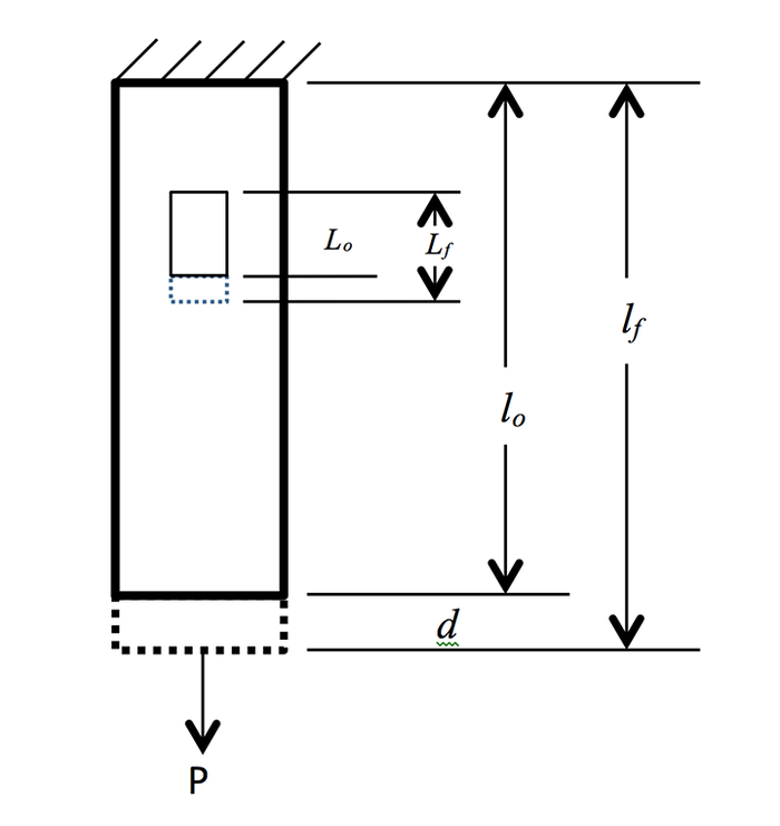
d = (Lf – Lo) x (lo/Lo)
Cantilever beams, defined as a continuous body fixed at one end and free at the other (see sketch below of Galileo’s famous cantilever beam), are commonly analyzed in undergraduate engineering courses. Although the analysis is somewhat oversimplified, many real-world structures can be approximated using the simple cantilever beam.

When a force is applied to the free end of the beam, the top surface of the beam becomes longer and the bottom surface becomes shorter. Obviously, these changes in surface dimension (related to strain) can easily be measured using bonded strain gages and the end-deflection calculated using Eq. (4) and the appropriate cantilever beam deflection equations.
Rather than designing for the actual surface strain experienced by such a structure under load, it is common to design the structure for minimal deflection. Consider an overhead crane system where the crane hoist moves on I-beams. If the I-beam is sized just so it does not fail under the approved load, there is a good chance that the beam will have excessive deflection, causing the moveable hoist to bind along its travel.
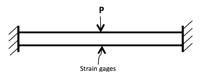
Such a design for an overhead crane hoist can be approximated using a beam with fixed ends (see sketch below). For this beam with a load placed center to its length, the maximum stress and maximum deflection for the beam are located at the point of load application and can be written as
σmax = -Pl/8I δmax = Pl3/192EI
Where:
P = applied load
l = beam length
E = Young’s modulus
I = section modulus
Note the deflection equation can be written as
δmax = - σmax x (l2/24EI) (5)
Strain is not normally required in failure theories of structural designs like an overhead crane system. But to ensure practical accuracy, the deflection of a beam can be calibrated against the surface strain measured under the point of load application using bonded strain gages (see diagram). Overly simplifying the relationship between stress and strain for a fixed-end beam, deflection can be approximated using Eq. (5) as
δmax = - ε x (l2/24I) (6)
If the instrumentation has sufficient range on the gage factor setting (relationship between resistance change and applied strain), then the instrument can be scaled using Eq. (6) to display deflection. For a more accurate measurement, the same setting can be used when calibrating deflection against known applied loads.
Strain gages can be used to measure velocity in several different ways. Much like measuring the deflection of a cantilever beam, perhaps one of the simpler methods is to instrument a paddle wheel device with strain gages and measure the static deflection associated with velocity of the air striking the paddle. The system deflection would be calibrated against a known speed to enhance accuracy. Obviously, this method is sensitive to wind gusts against the paddle, but spikes in the data caused by gusts can be masked using time-based filtering.
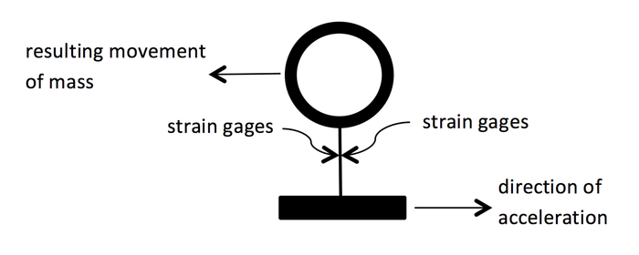
Acceleration can easily and accurately be measured using strain gages. A known mass is supported by a suitable beam and the beam instrumented with bonded strain gages. As the mass is accelerated, the beam bends and the amount of bending is proportional to the acceleration (see simplified sketch below). Strain gages indicate the amount of bending and the readout instrument is scaled to read in units of acceleration (m/s2).
As a side note, this same concept can be used to accurately measure liquid density.
Two graduate students at Colorado State University needed a quick, simple, yet fairly accurate method for determining liquid density. As shown in the two pictures below, a ping pong ball is attached to a rod, which is then attached to a thin aluminum cantilever beam.
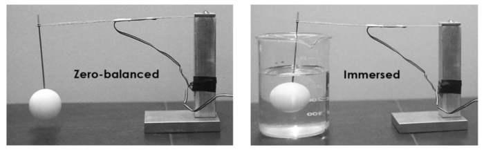
Strain gages are bonded a fixed distance away from the rod and the instrument zero balanced with the ping pong ball hanging freely in air. When the ping pong ball is submerged into a liquid, the cantilever beam deflects by an amount proportional to the density of the liquid. The strains indicated by the gages are proportional to the deflection and, therefore, to the liquid density. This is a good example of using what you can measure to learn something about what you can’t measure – or, at least, measure simply.


Recent comments