

The Clamping Clinic
One aspect of the strain gage sensor bonding procedure that sometimes is short-changed in the process of installation, is proper strain gage clamping. With adhesively bonded strain gages, the strain in the test surface must be transmitted to the gage backing and grid via the adhesive. To ensure that this occurs with accuracy and stability, there are stringent requirements on both the adhesive and the bonding technique. Foil strain gage manufacturers supply adhesives that are specially formulated or selected for strain gage bonding to ensure excellent strain transmission characteristics. But the full capability of the adhesive can only be realized if it is cured under conditions that produce a thin, uniform film of adhesive between the test surface and the gage backing.
All organic foil strain gage adhesives require application and maintenance of some form of clamping pressure throughout the curing stage. In the case of the popular, fast-curing Micro-Measurements M-Bond 200 adhesive, clamping pressure is easily applied with the thumb or finger, and pressure only needs to be maintained for about a minute. However, M-Bond 200 is not recommended for elevated-temperature or long-term strain measurements. For these applications, or when gages must be installed in confined areas, such as inside of tubing or board holes, epoxy or epoxy-phenolic adhesives are commonly selected. With epoxy-based adhesives it is always necessary to maintain a specified uniform clamping pressure while the adhesive is curing. The instruction bulletins accompanying all Micro-Measurements strain gage adhesives include, in each case, the recommended clamping pressure and curing cycle. Since the curing process usually takes several hours, and may involve elevated temperatures, it is important that the clamping device is physically stable and capable of holding the specified force for the required time.
The mechanical arrangement used to obtain steady, non-shifting clamping force obviously depends on the nature of the test object and the gage installation. Sometimes a simple spring clamp will suffice. In other cases, it may be necessary to devise a more elaborate clamping fixture.
For any type of clamp, the assembly typically consists of 3 components:
-
A silicone rubber pad over the strain gage to distribute the clamping pressure uniformly.
-
A metal back-up plate over the rubber pad.
- A means of applying steady force with a dead weight or clamp. The clamping pressure is calculated by dividing the applied force by the surface area of the rubber pad in contact with the strain gage and specimen surface.
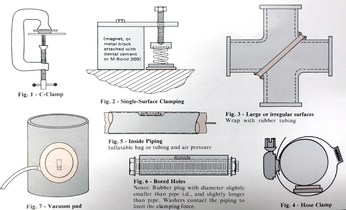
A selection of representative gage clamping techniques is shown in the sketches above. Whether one of these or another clamping scheme is used, there are two precautions which need to be observed in every case.
The first is to always apply the clamping force through some form of spring (preferably low-rate). Rigid clamps (C-clamps, hose clamps, etc.), such as those shown in Figs. 1 and 2, should never be used without a spring in series with the clamping force. The spring is necessary to ensure that the force doesn’t vary significantly with small dimensional changes which may occur as the adhesive flows and cures, or as the temperature changes. The second is to always provide a means for determining the actual clamping force; and thus making certain that it is within the range specified by the supplier. This can be done by pre-calibrating the spring for force versus deflection, or by direct measurement on the clamping assembly with an inexpensive spring scale, e.g., a “fish scale”. The latter technique is particularly appropriate for arrangements such as those shown in Fig. 3 and 4.
Heat shrinkable tubing should not be used to apply clamping force to a strain gage during the adhesive cure. Heat shrinkable materials shrink and conform to a surface, but they will not apply a force to the strain gage since these materials are very soft while hot.
More information about Strain Gage Clamping Techniques is available in Micro-Measurements Tech Tip TT-610:
http://www.vishaypg.com/docs/11090/tt610.pdf
Clamping Hardware: http://www.vishaypg.com/docs/11021/insttool.pdf


Recent comments