
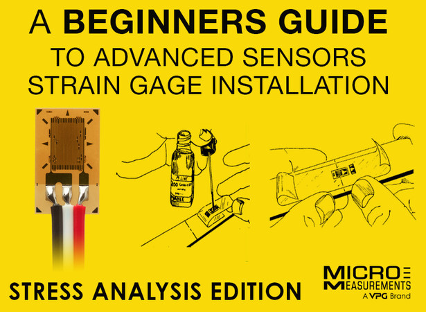
ADVANCED SENSORS TECHNOLOGY STRAIN GAGE INSTALLATION (STRESS ANALYSIS)
Micro-Measurements Certified M-Bond 200 is an excellent general-purpose laboratory adhesive because of its fast room-temperature cure and ease of application. When properly handled and used with the appropriate strain gage, M-Bond 200 can be used for high-elongation tests in excess of 50,000 microstrain (µε) , for fatigue studies, and for one-cycle proof tests up to +200 °F [+95 °C] or down to -300 °F [-185°C]. The normal operating temperature range is -25° to +150°F [-30° to +65°C]. M-Bond 200 is compatible with all Micro-Measurements strain gages and most common structural materials. When bonding to plastics, we recommend testing a small sample area to ensure compatibility. For best reliability, it should be applied to surfaces between the temperatures of +70° and +85°F [+20° to +30°C], and in a relative humidity environment of 30% to 65%.
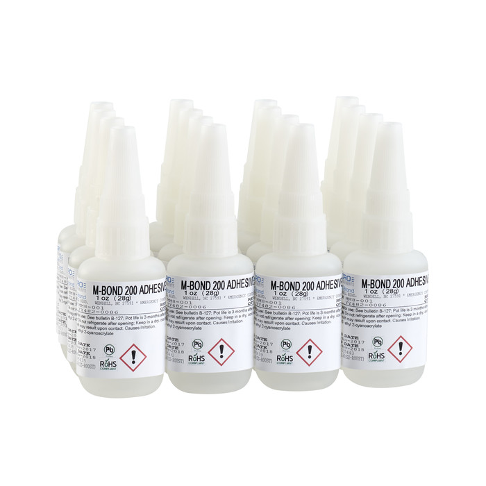
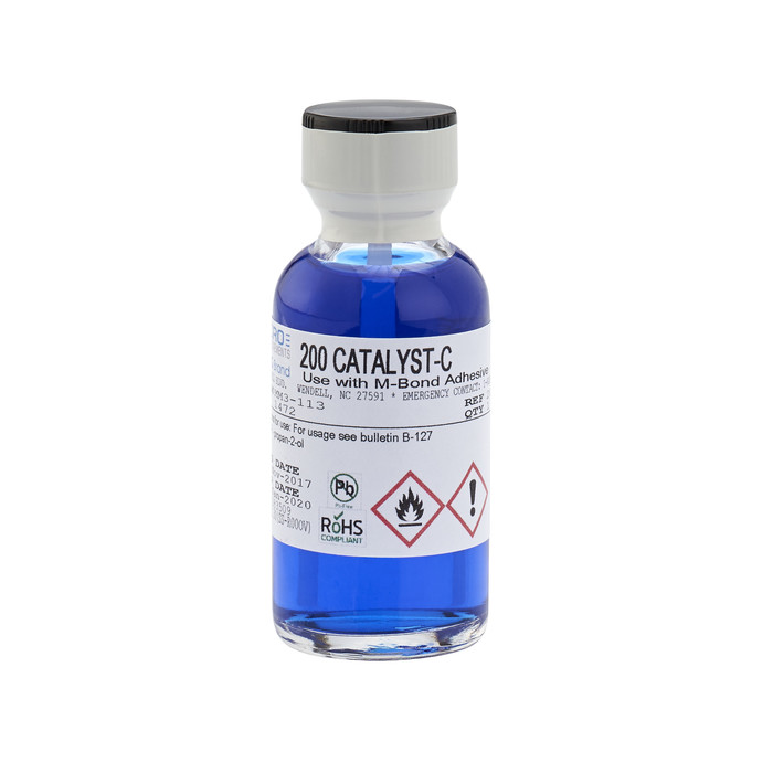
M-Bond 200 catalyst has been specially formulated to control the reactivity rate of this adhesive. The catalyst should be used sparingly for best results. Excessive catalyst can contribute many problems; e.g., poor bond strength, age-embrittlement of the adhesive, poor glueline thickness control, extended solvent evaporation time requirements, etc.
Since M-Bond 200 bonds are weakened by exposure to high humidity, adequate protective coatings are essential. This adhesive will gradually become harder and more brittle with time, particularly if exposed to elevated temperatures. For these reasons, M-Bond 200 is not generally recommended for installations exceeding one or two years. (Typically not more than one year).
For proper results, the procedures and techniques presented here should be used with qualified Micro-Measurements installation accessory products. Those used in this procedure are:
- CSM Degreaser or GC-6 Isopropyl Alcohol
- Silicon Carbide Paper
- M-Prep Conditioner A
- M-Prep Neutralizer 5A
- GSP-1 Gauze Sponges
- CSP-1 Cotton Applicators
- PCT Gage Installation Tape
SHELF AND STORAGE LIFE
M-Bond 200 adhesive has a minimum pot life of three months at +75°F [+24°C] (not to exceed the date of expiration) after opening and with the cap placed back onto the bottle immediately after each use.
Note: To ensure the cap provides a proper seal, the bottle spout should be wiped clean and dry before replacing the cap.
Unopened M-Bond 200 adhesive may be stored up to nine months at +75°F [+24°C] or twelve months at +40°F [+5°C].
Note: Condensation will rapidly degrade adhesive performance and shelf life; after refrigeration the adhesive must be allowed to reach room temperature before opening, and refrigeration after opening is not recommended.
HANDLING PRECAUTIONS
M-Bond 200 is a modified alkyl cyanoacrylate compound. Immediate bonding of eye, skin or mouth may result upon contact. Causes irritation. The user is cautioned to: (1) avoid contact with skin; (2) avoid prolonged or repeated breathing of vapors; and (3) use with adequate ventilation. For additional health and safety information, consult the Safety Data Sheet, which is available upon request.
GAGE APPLICATION TECHNIQUES (11 steps)
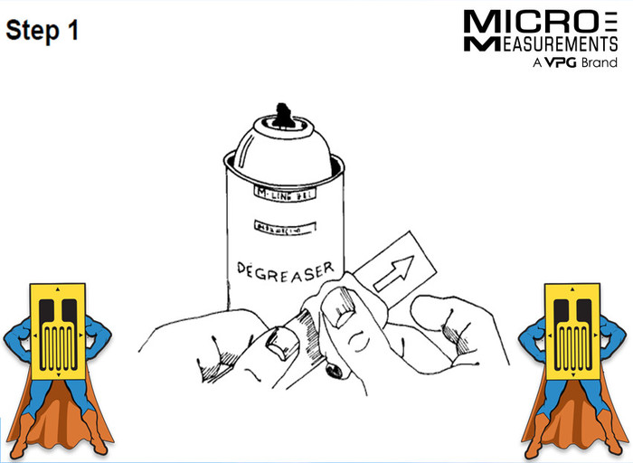
Step 1
Thoroughly degrease the gaging area with solvent, such as CSM Degreaser or GC-6 Isopropyl Alcohol. The former is preferred, but there are some materials (e.g., titanium and many plastics) that react with strong solvents. In these cases, GC-6 Isopropyl Alcohol should be considered. All degreasing should be done with uncontaminated solvents-thus the use of “one-way” containers, such as aerosol cans, is highly advisable.
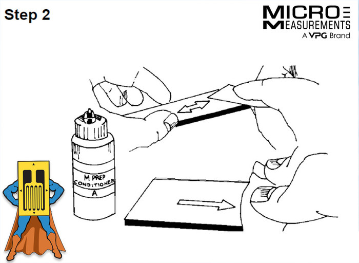
Step 2
Preliminary dry abrading with 220- or 320-grit silicon-carbide paper is generally required if there is any surface scale or oxide. Final abrading is done by using 320-grit silicon-carbide paper on surfaces thoroughly wetted with M-Prep Conditioner A; this is followed by wiping dry with a gauze sponge. Repeat this wet abrading process with 400-grit silicon-carbide paper, then dry by slowly wiping through with a gauze sponge. Finish with 320 grit on most steels and 400 grit on aluminum alloys. Using a 4H pencil (on aluminum) or a ballpoint pen (on steel), burnish (do not scribe) whatever alignment marks are needed on the specimen. Repeatedly apply M-Prep Conditioner A and scrub with cotton-tipped applicators until a clean tip is no longer discolored. Remove all residue and Conditioner by again slowly wiping through with a gauze sponge. Never allow any solution to dry on the surface because this invariably leaves a contaminating film and reduces chances of a good bond.
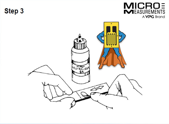
Step 3
Now apply a liberal amount of M-Prep Neutralizer 5A and scrub with a cotton-tipped applicator. With a single, slow wiping motion of a gauze sponge starting within the clean area and wiping outward in one direction. Repeat the wiping step with a clean gauze pad, again, start in the clean area, wipe though the gage location moving outward in a single stroke to fully dry this surface. Do not wipe back and forth because this may allow contaminants to be redeposited.
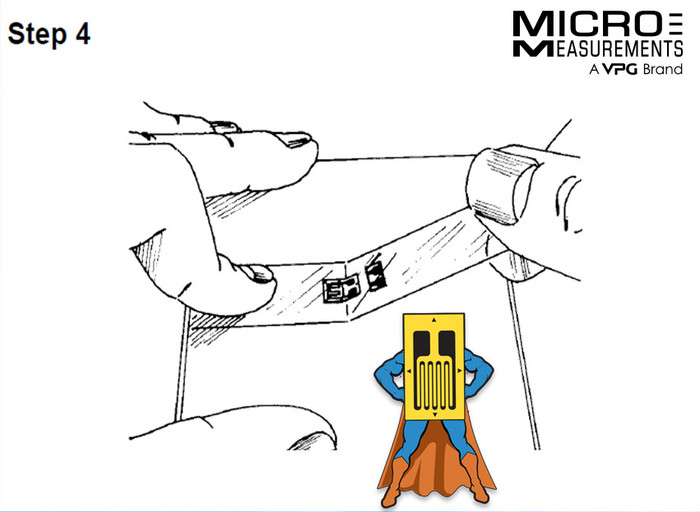
Step 4
Using tweezers to remove the gage from the transparent envelope, (handle the gage by the edge of the matrix avoiding contact with the gage foil if at all possible. When it is necessary to touch the gage foil , do so at the solder pads and not in the sensing grid area). Place the gage, bonding side down, (matte finish side) on a chemically clean glass plate or gage box surface. If a solder terminal will be used, position it on the plate adjacent to the gage as shown. A space of approximately 1/16 in [1.6 mm] or more where space allows or application requires should be left between the gage backing and terminal. Place a 4- to 6-in [100- to 150-mm] piece of Micro-Measurements PCT gage installation tape over the gage and terminal. Take care to center the gage on the tape. Carefully lift the tape at a shallow angle (about 45 degrees or less to specimen surface), bringing the gage up with the tape as illustrated above.
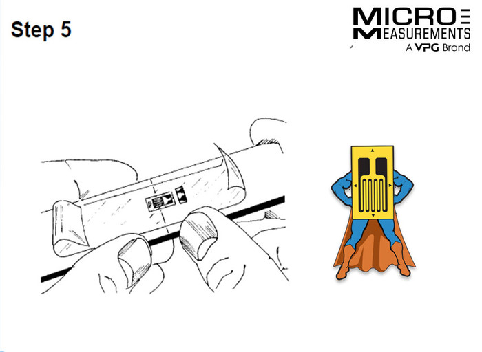
Step 5
Position the gage/tape assembly so that the triangle alignment marks on the gage are over the layout lines on the specimen. If the assembly appears to be misaligned, lift one end of the tape at a shallow angle until the assembly is free of the specimen. Realign properly, and firmly anchor at least one end of the tape to the specimen. Realignment can be done without fear of contamination by the tape mastic if Micro-Measurements PCT gage installation tape is used, because this tape will retain its mastic when removed.
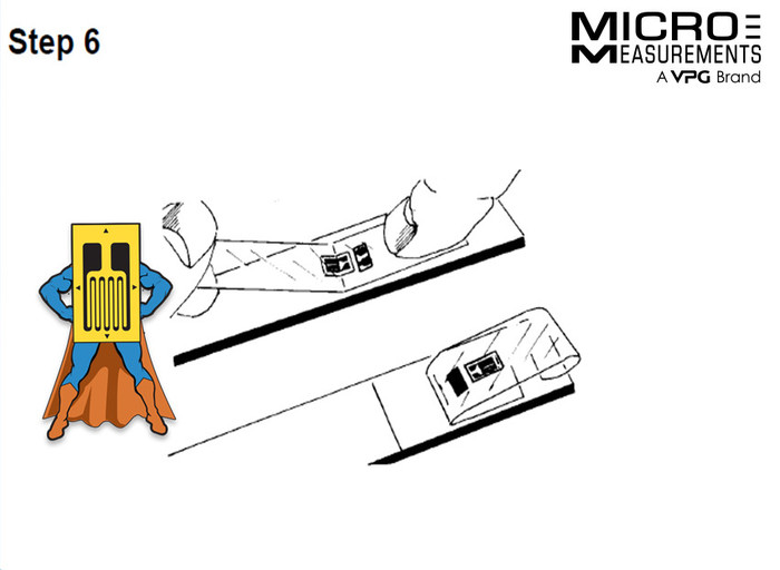
Step 6
Lift the gage end of the tape assembly at a shallow angle to the specimen surface (again at 45 degrees or less) until the gage and terminal are free of the specimen surface. Continue lifting the tape until it is free from the specimen approximately 1/2 in [10 mm] beyond the terminal. Tuck the loose end of the tape under and press to the specimen surface so that the gage and terminal lie flat, with the bonding surface exposed.
Note: Micro-Measurements gages have been treated for optimum bonding conditions and require no pre-cleaning before use unless contaminated during handling. If contaminated, the back of any gage can be cleaned with a cotton-tipped applicator slightly moistened with M-Prep Neutralizer 5A.
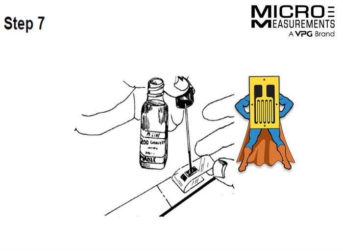
Step 7
M-Bond 200 catalyst can now be applied to the bonding surface of the gage and terminal. M-Bond 200 adhesive will harden without the catalyst, but less quickly and reliably. Very little catalyst is needed, and it should be applied in a thin, uniform coat. Lift the brush-cap out of the catalyst bottle and wipe the brush approximately 10 strokes against the inside of the neck of the bottle to wring out most of the catalyst. Set the brush down on the gage and swab the gage backing. Do not stroke the brush in a painting style, but slide the brush over the entire gage surface and then the terminal. Move the brush to the adjacent tape area prior to lifting from the surface. Allow the catalyst to dry at least one minute under normal ambient conditions of +75°F [+24°C] and 30% to 65% relative humidity before proceeding.
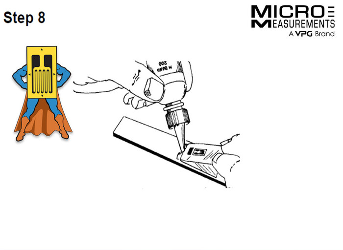
Note: The next three steps (8, 9 and 10) must be completed in the sequence shown, within 3 to 5 seconds. Read Steps 8, 9, and 10 before proceeding.
Step 8
Lift the tucked-under tape end of the assembly, and, holding in the same position, apply one or two drops of M-Bond 200 adhesive (typically one drop is more than sufficient) at the fold formed by the junction of the tape and specimen surface. This adhesive application should be approximately 1/2 in [13 mm] outside the actual gage installation area. This will insure that local polymerization that takes place when the adhesive comes in contact with the specimen surface will not cause unevenness in the gage glueline.
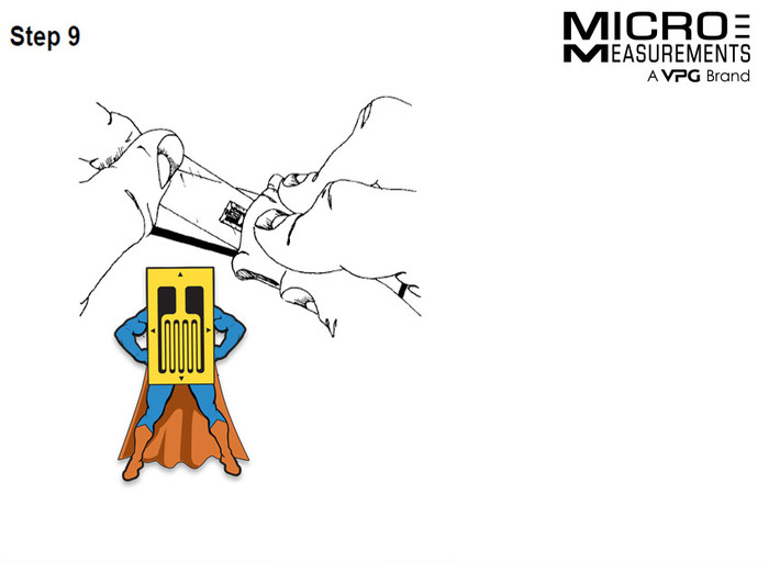
Step 9
Immediately rotate the tape to approximately a 30-degree angle so that the gage is bridged over the installation area. While holding the tape slightly taut, slowly and firmly make a single wiping stroke over the gage/tape assembly with a piece of gauze bringing the gage back down over the alignment marks on the specimen. Use a firm pressure with your fingers when wiping over the gage. A very thin, uniform layer of adhesive is desired for optimum bond performance.
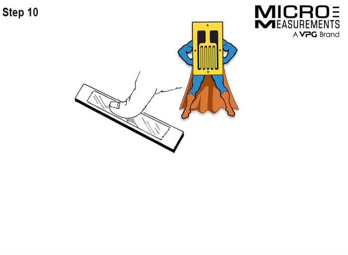
Step 10
Immediately upon completion of wipe-out of the adhesive, firm thumb pressure must be applied to the gage and terminal area. This pressure should be held for at least one minute. In low-humidity conditions (below 30%), or if the ambient temperature is below +70°F [+20°C], this pressure application time may have to be extended to several minutes. Where large gages are involved, or where curved surfaces such as fillets are encountered, it may be advantageous to use preformed pressure padding during the operation. Pressure-application time should again be extended due to the lack of “thumb heat” which helps to speed adhesive polymerization. Wait two minutes before removing tape.
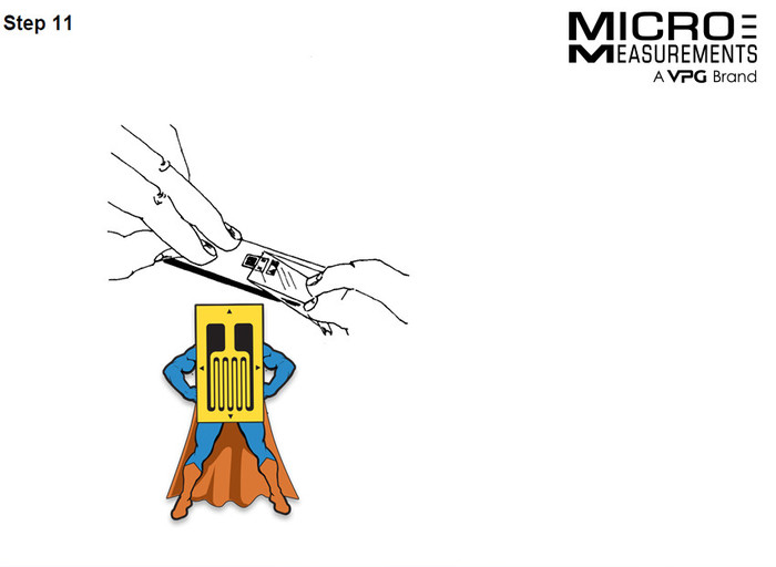
Step 11
The gage and terminal strip are now solidly bonded in place. It is not necessary to remove the tape immediately after gage installation. The tape will offer mechanical protection for the grid surface and may be left in place until it is removed for gage wiring. To remove the tape, pull it back directly over itself, peeling it slowly and steadily off the surface. This technique will prevent possible lifting of the foil on open-faced gages or other damage to the installation.
FINAL INSTALLATION PROCEDURE
- Select appropriate solder and attach leadwires. Prior to any soldering operations, open-faced gage grids should be masked with PDT drafting tape to prevent possible damage.
- Remove the solder flux with Rosin Solvent, RSK-1.
- Select and apply protective coating according to the protective coating selection chart found in the Micro-Measurements Strain Gage Accessories Data Book found at http://www.vishaypg.com/micro-measurements/databooks/


Comments
Un retour sur les bases pour rester à la page
No vale cualquier adhesivo